Electronic Circuit Diagram
Channel Reputation Rank
Activity Status
Stale
last updated
Category
Circuit Archives
Enter a key term, phrase, name or location to get a selection of only relevant news from all RSS channels.
Enter a domain's or RSS channel's URL to read their news in a convenient way and get a complete analytics on this RSS feed.
Unfortunately Electronic Circuit Diagram has no news yet.
But you may check out related channels listed below.
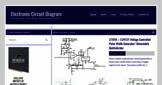
[...] The schematic diagram below show a circuit of high voltage generator. This circuit uses a 4049 hex inverter as an [...]
[...] The schematic diagram below describes a simple continuity tester circuit. This circuit is used to test if two [...]
[...] A compressor circuit shown in the schematic diagram below can produce consistent output of 1.4V P-P over entire 60dB range that is very useful [...]
[...] The voltmeter shown in the schematic diagram below has very high impedance. The range selector uses conventional voltage divider [...]
[...] This is a schematic diagram of video amplifier circuit with bi-phase output. Bi-phase output provides both positive-going and negative-going [...]
[...] This is a video amplifier circuit featured with controllable variable gain. The control is done by adjusting the voltage [...]
[...] in guitar effect pedals. Tremolo effect is produced if we modulate the amplitude of an audio signal. The shape of modulating signal can vary from square wave, sawtooth, or sine. When we use a [...]
[...] transistor instead of integrated circuit. This circuit can be used for frequency range of audio signal 20-20kHz . The output signal which pass trough active device is AC signal with zero average [...]
[...] This is a schematic diagram of video amplifier circuit with bi-phase output. Bi-phase output provides both positive-going and negative-going signal, and can be used as balanced signaling. [...]
[...] is determined by choosing the right components values for certain application. With this circuit schematic diagram, we ...[Read More] [...]
[...] in the schematic diagram below, we can control the low-level audio signals with ±3V variable DC voltage. This attenuator circuit uses a field effect transistor (FET) to shunt the signal to [...]
[...] with a constant load, since there will be no regulation in such case. What we call CVCS regulator is a regulator with two modes. The first mode is constant voltage, where the regulator [...]
[...] NiMH batteries can be used to produce 3V/3.3V supply voltage. This can be done by this linear regulator circuit. This circuit uses an ICL7611 micropower op amp and MAX872 voltage reference. This [...]
[...] When we modulate a carrier signal with amplitude modulation, there will be four frequency components as the result. The first is the modulating signal itself, the second is the frequency [...]
[...] The schematic diagram below show a circuit of high voltage generator. This circuit uses a 4049 hex inverter as an [...]
[...] The schematic diagram below describes a simple continuity tester circuit. This circuit is used to test if two [...]
[...] A compressor circuit shown in the schematic diagram below can produce consistent output of 1.4V P-P over entire 60dB range that is very useful [...]
[...] The voltmeter shown in the schematic diagram below has very high impedance. The range selector uses conventional voltage divider [...]
Related channels
-
Electronic Circuits Diagrams, Electrical Engineering News and Resources
Electrical engineering news, resources, electronic design projects, circuit diagrams and diy projects with schematic for...
-
Dataarchitectoo
Architecture Diagram and Schematic Buildings
-
Free Electronic Circuits
simple and hobby Electronic circuits diagrams and more schematic
-
Electronic Schematic Circuit Diagram - CircuitsTune
A birth place of electronic schematic circuit diagram